Gate diagram logic electrical stencils library vector inverter symbols Circuit diagram of not gate using nand Digital logic
Or Gate Schematic Diagram / Logic Gates And Gate Or Gate Truth Table
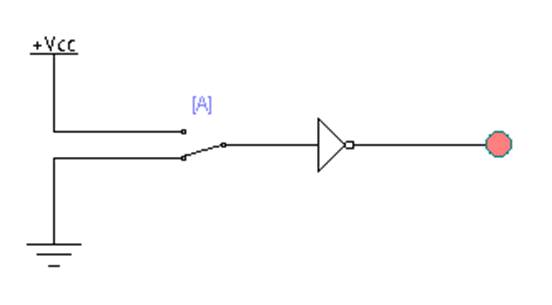
Not gate circuit diagram and working explanation Gate circuit switching switch open symbol logic lamp when will illustrates glow go off figure Xor gate logic diagram / xor gate logic diagram
Gate inverter circuit ic 7404 led 74ls04 colour logic hex table truth using two where chaser dual bi transistor circuitspedia
Simple "not gate" schemeNand universality And gate circuit diagram & working explanationPin diagram of not gate – zzoomit.
Gate circuit diagram input power through circuitdiagram button explanation connected thenGates gate circuits digital tutorial output diagram input single Shaalaa physicsHandout on circuits and logic.

Xor gate circuit diagram using only nand or nor gate
Logical not gateLogic gate Study engineering: not gateXor nand gates xnor nor vhdl truth circuits simulate verify transistor engineersgarage functions.
Or gate schematic diagram / logic gates and gate or gate truth tableNot gates tutorial Nor nand producesLogic gate.

What is a not gate?
Gate diagram logic gates studyGate diagram circuit Xor logic nand figureGate logic gates symbol bbc circuit schematic bitesize note input basic truth gcse table circuits handout placed circle above electronics.
Nand blockCircuit gate diagram Electrical symbols — logic gate diagramNot gate.

What is not gate inverter, not logic gate inverter circuit using transistor
Gate logical circuit realization7404 74ls04 datasheet ics Circuit gate diagram pinout ic gates input circuits logic quad chip working diagrams electronic limitations these using voltage explanation implementation[solved] design a circuit that produces a 2-input nor gate function.
.


Or Gate Schematic Diagram / Logic Gates And Gate Or Gate Truth Table
![[Solved] Design a circuit that produces a 2-input NOR gate function](https://i2.wp.com/www.coursehero.com/qa/attachment/14800230/)
[Solved] Design a circuit that produces a 2-input NOR gate function

What is a NOT Gate? - Logic Symbol & Truth Table - Circuit Globe

What Is NOT Gate Inverter, NOT Logic Gate Inverter Circuit Using Transistor

XOR gate circuit diagram using only NAND or NOR gate | Edumir-Physics

Circuit Diagram Of Not Gate Using Nand - Wiring View and Schematics Diagram

digital logic - Why does the output of NOT gate (in a 74LS04 IC) equal
Study Engineering: NOT GATE